Two-level, Slew-rate Control Simplifies Drives Inverter Using Discrete IGBTs in Parallel
Infineon’s two-level, slew-rate control (2L-SRC) gate driver IC enables a reduction of the number of paralleled IGBTs through a slew-rate-control technique.
The current capability of a discrete IGBT with a co-packed freewheeling diode is limited compared to the capability of power modules. Therefore, discrete IGBTs are used in parallel to increase the output power. This often reduces the switching performance to achieve an even current distribution of paralleled IGBTs.
Introduction
The use of discrete IGBTs is a suitable solution for many power electronic systems. A collector current rating of 40 A is widely available from several suppliers. Therefore, paralleling discrete IGBTs is very popular in lower power systems, such as drives, for increasing the output power. However, paralleling IGBTs is not simple. Circuits with paralleled discrete IGBTs can suffer for example from unequal collector current distribution.
It would be easier, if a single IGBT could be used instead of, for example, two switches. The TO-247PLUS package of Infineon can provide, for example, a collector current of 75 A. Such a device can be almost identical in theory with two 40-A IGBT in conventional TO-247 packages from electrical point of view considering the previously mentioned limitations. However, a single TO-247PLUS package has a higher thermal resistance than two conventional TO-247 packages in parallel.
Using Infineon’s 2L-SRC gate driver IC 1ED3240MC12H can reduce the losses of the single 75-A IGBT such that the thermal disadvantage is equalized and a large system level simplification can be achieved.
1ED3240MC12H Family Optimizes Switching Losses
Figure 1 depicts the typical circuit for the proposed gate-drive circuit for a half bridge using an integrated gate-drive IC. The IC has two output terminals. Both outputs can be configured having individual turn-on gate resistors and turn-off gate resistors, for example R1/R2 and R3/ R4. Therefore, you can achieve almost any switching performance.
The first terminal OUT performs all switching events that are controlled by the input terminal IN. The second output terminal OUTF is activated based on the status of the second control input terminal /INF. OUTF is activated for turn-on together with OUT, if the level of /INF is low. Output OUTF is activated during turn-off, if the level of /INF is high. In cases where OUTF does not contribute to the turn-on or turn-off event, it stays in a high-impedance state during the switching transient of the power switch. Thus, the proposed 2L-SRC concept inherently anticipates the switching behavior of power transistors depicted in Figure 2.
Double Pulse Characterization Results
Double pulse tests capture the switching properties of power switches. Figure 2 shows examples of the turn-on energies Eon and the collector-emitter voltage slew rates dvCE/dt of the discrete IGBTs under test. The values of the two IKW40N120T2 in parallel are displayed on the right in Figure 2 and are derived by scaling from a measurement of a single IKW40N120T2. The thermal resistance and capacitance of the two parallel TO-247 packages have been scaled, too. Please note that the scaling method usually results in a more optimistic model, as detrimental effects of paralleling of paralleled IGBT cannot be considered by scaling. The results of the IKQ75N120CT2 devices under test can be seen on the left of Figure 2. The selection of gate resistors listed in Table 1 is based on these results.
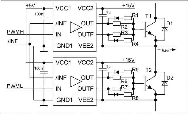
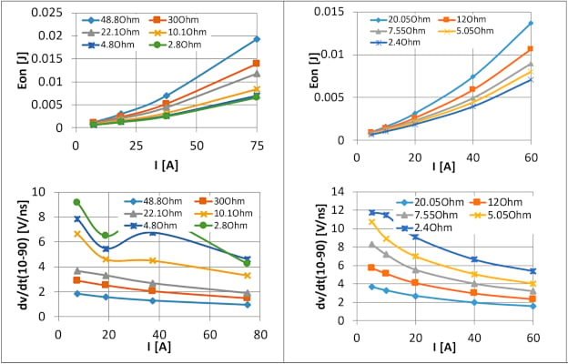
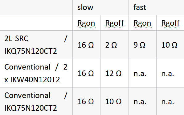
Table 1. Gate resistor selection for simulation.
System Simulation Results
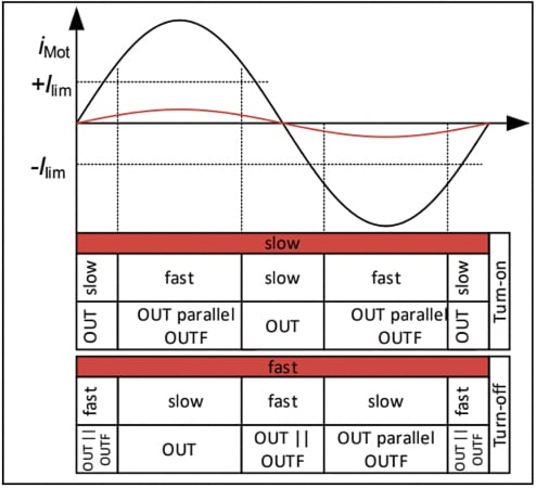
Figure 3 shows the areas of slow mode and fast mode over a motor-current period. The signal change at terminal /INF happens at a defined value of the motor current. The IC operates in slow mode when the motor current is below the limit |Ilim| and in fast mode when it is above |Ilim|. The system controller generates the signal /INF. The change of the /INF signal is based on the instantaneous phase current of a motor drive. However, it is not limited to it. Other decision-relevant signals can include e.g. the heat sink temperature or the power switch temperature.
Furthermore, there can be no changes in the modes at all, if the motor-current amplitude stays continuously below the limit value |Ilim|. This case is displayed in the brown curve.
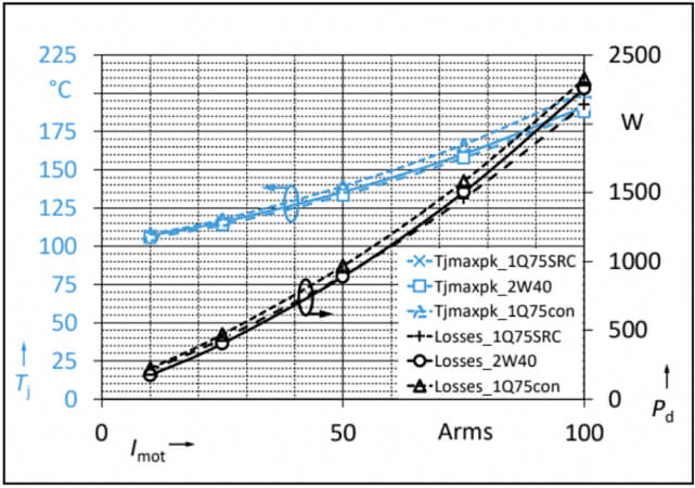
The simulation is performed at a DC-link voltage of VDC = 560 V, a switching frequency of fp = 16 kHz, a fixed heat sink temperature of THS = 100°C and sinewave modulation with a motor frequency of fMot = 50 Hz and the motor’s power factor of cos phi = 0.8. The selection of the gate resistors ensures that dvCE/dt does not exceed 5 V/ns at 10% of the nominal current Inom. The changeover current was selected for |Ilim| = 15 A.
Figure 4 shows the simulation results under the described conditions. Three cases were simulated. The dashed line depicts the proposed gate-drive scheme using TO-247PLUS package (“1Q75SRC”). The solid line (“2W40”) represents the two IGBTs in parallel using the conventional gate drive. Any slow-down of the switching speed to achieve an equal current distribution is disregarded here. Hence, the results are optimistic in this case. Third, the pointed lines show the results of the TO-247PLUS using the conventional gate-drive scheme (“1Q75con”). It can be seen that the junction temperature of the single IGBT in the TO-247PLUS package using 2L-SRC is very similar to the junction temperature of the two IGBTs in the paralleled conventional TO-247 package. Both solutions outperform the TO247PLUS with conventional gate drive by approximately 8 - 10 A r.m.s at a given junction temperature of Tj = 175°C (blue curves). This is an improvement of 10%. Furthermore, the losses of the proposed slew-rate control gate drive result in lower overall power losses, even in comparison to the two conventional TO-247 packages in parallel.
Conclusion
The 1ED3240MC12H gate driver IC family enables lower losses overall by reducing the switching losses. Simulations based on double pulse measurements show that a single 75-A IGBT can replace two 40-A IGBTs in parallel in drive systems without derating the overall output power capability.
Furthermore, the 1ED3240MC12H family can even increase the application’s output power. Thus, Infineon’s 2L-SRC gate driver 1ED3240MC12H is able to reduce the complexity of drive systems that use two or more IGBTs in parallel.
Finally, 2L-SRC IC 1ED3240MC12H offers more upside potential, as derating of parallel IGBTs has not been considered in the simulations yet. This leads to optimal performance of the conventional setup. Therefore, the two-level slew-rate control can even outperform conventional paralleled IGBTs in terms of the maximum motor current.