3.3 kV IGBT4 Opens New Horizons in Power Density
The latest 3.3 kV IGBT4 and EC4 technology with high electrical robustness has enabled modules with rated currents up to 2400 A in IHV housings – B series.
The features of these new modules are especially attractive for applications such as traction, medium-voltage drives (MVD) and high-voltage DC transmission (HVDC), where the focus is on high power density without compromising service life.
One of the most common trends in power electronics is the permanent increase in power density. This trend is observed in demanding applications like traction, medium-voltage drives and high-voltage DC transmission, which also have strict requirements in regards to electrical robustness and reliability. To meet the latest application requirements, Infineon has developed the 3.3 kV IGBT4 and EC4 technology with increased current density, high electrical robustness, and twice the power-cycling capability of the 3.3 kV IGBT3 generation.
3.3 kV IGBT4 and EC4 technology with high electrical robustness
The new 3.3 kV IGBT4 and EC4 chip set has been developed for up to 60 percent higher current density per IHV B as compared to IGBT3 modules with the same housing footprint – 190 x 140 mm (Figure 1) and maximum feasible current density. As a result, the nominal current rating is increased from 1500 A for the IGBT3 generation to 2400 A for the IGBT4 generation. A further module in the 3.3 kV IGBT4 portfolio has a nominal current rating of 1600 A in a smaller housing with a footprint of 130 x 140 mm. Thus, the current density of this module is 56 percent higher than the current density of the 1500 A module from the previous generation. A doubling of the power density is achievable when you compare the 1200 A IGBT3 module and 2400 A IGBT4 module in the same housings.
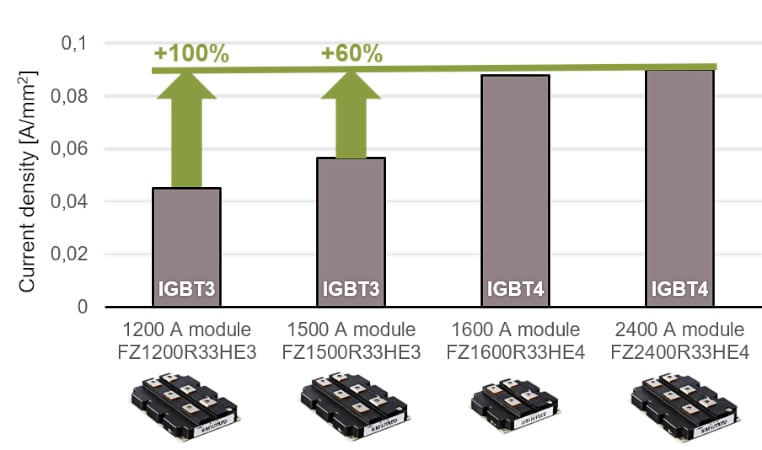 Figure 1. Current density increase in the latest 3.3 kV IGBT4 modules.
Such a drastic current density increase has been achieved by the redesign of the substrate layout and the internal interconnection layout, which provides more space for the die attach, thus enabling an increase in active area. Together with an optimized emitter concept for the IGBT4, this results in significantly reduced static losses. The EC4 features a different emitter concept combined with a reduced thickness to ensure low static diode losses [1].
Increasing the current density also requires high electrical robustness of the new chip set under switching conditions. Therefore, the 3.3 kV IGBT4 technology has been developed to ensure a 4800 A turn-off current for the 2400 A module. A detailed analysis of the inherent destruction limit, combined with an adjusted turn-off speed for the 1600 A and 2400 A modules, has enabled the modules to achieve outstanding electrical reverse bias safe operating area (RBSOA) robustness. The switching diagram with 2 x Inom commutated current shown in Figure 2 demonstrates the high RBSOA robustness of the 2400 A module.
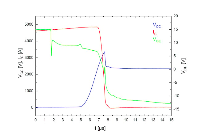
Figure 2. FZ2400R33HE4 turn-off diagram at IC = 4800 A, VCE = 2400 V.
High-rated current usually results in increased power dissipation of the diode. Therefore, the 2400 A IGBT4 module offers a 125 percent increase in the safe operating area (SOA) limit of the diode compared to the 1500 A IGBT3 module [2,3]. Figure 3 shows recovery diagrams with high di/dt at VCE = 2400 V and IC = 4800 A. This demonstrates a reverse-recovery power peak up to PRQM = 5.4 MW within the SOA limits.
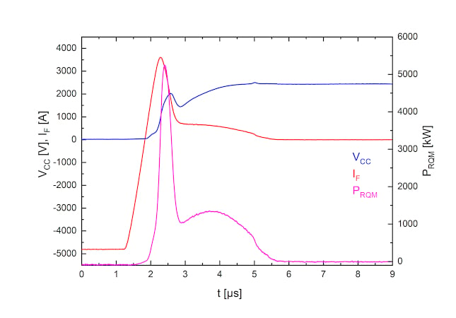
Figure 3. FZ2400R33HE4 diode turn-off diagram at IR = 4800 A, VCE = 2400 V.
3.3 kV IGBT4 modules in traction applications
Traction is one of the most demanding applications for power semiconductors. The high demand for acceleration and deceleration leads to challenging performance requirements in terms of current per module. In addition, the high frequency of starts and stops results in aging effects within the IGBT module, which should function reliably in the field during its typical lifetime of 30 years [4]. Doubling the power-cycling capability of the modules with the latest IGBT4 and EC4 diode technology is an important feature for traction applications. It enables an increase of the junction temperature cycle and, as a result, peak junction temperatures for IGBT4 modules in the applications that are limited by power-cycling capability.
In Figure 4 there are two power-cycling diagrams vs. the junction temperature cycle ΔTvj for 3.3 kV IGBT3 and IGBT4 IHV B modules, respectively. For the application example shown in Figure 4, ΔTvj is defined at 50 K for the IGBT3 module, and at 58 K for the IGBT4 module. Assuming that the junction temperature drops to the ambient temperature TAMB = 50°C at every load cycle, the peak junction temperature of IGBT3 modules would be limited to 100°C, and 108°C for IGBT4 modules. The delta of 8°C indicates twice the power-cycling capability of the IGBT4 modules.
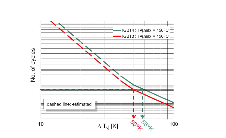
Figure 4. Power-cycling diagrams for 3.3 kV IGBT3 and IGBT4 IHV B modules.
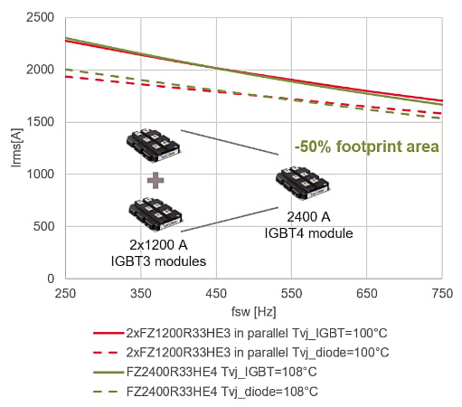
Figure 5. Electrical performance benchmark of two FZ1200R33HE3 modules vs. one FZ2400R33HE4 under the following conditions: VCC = 1800 V, TAMB = 50°C, fout = 50 Hz, m = 0.9, cos φφ = 1 (IGBT benchmark), cos φφ = -1 (diode benchmark).
Based on these application conditions, electrical performance simulations for a two-level topology are performed in IPOSIM with highly efficient, liquid-cooled heat sinks (RthHA = 5 K/KW for IHV B 190 x 140 mm and RthHA = 7 K/kW for IHV B 130 x 140 mm). The application example (see Fig. 5) provides an electrical performance comparison of two parallel 1200 A IGBT3 modules FZ1200R33HE3 with a 2400 A IGBT4 module FZ2400R33HE4. It can be seen that the output RMS current capability of one 2400 A IGBT4 module is the same as two 1200 A IGBT3 modules in parallel.
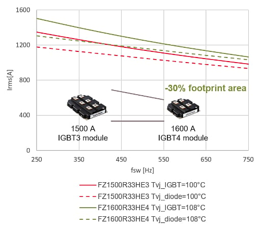
Figure 6. Electrical performance benchmark of FZ1500R33HE3 vs. FZ1600R33HE4 under the following conditions: VCC = 1800 V, TAMB = 50 °C, fout = 50 Hz, m = 0.9, cos φφ = 1 (IGBT benchmark), cos φφ = -1 (diode benchmark).
The second example (see Figure 6) shows the feasibility of replacing a 1500 A IGBT3 module FZ1500R33HE3 (190 x 140 mm footprint) with a 1600 A IGBT4 module FZ1600R33HE4 in a smaller housing with 130 x 140 mm footprint. Output RMS current capability of the 1600 A IGBT4 module is 4 to 10 percent higher than the 1500 A IGBT3 module that has a bigger housing, proving that a reduction in the heat sink area of up to 30 percent is feasible.
The latest 3.3 kV IHV B modules, based on the IGBT4 and EC4 diode technology with high electrical robustness, demonstrate outstanding performance in demanding applications that are limited by power-cycling capability. The 1600 A IGBT4 module can replace the 1500 A IGBT3 module, and thereby reduce the size of the housing. One 2400 A IGBT4 module can eliminate the parallel connection of two IGBT3 modules with current rating 1200 A.